

With the release of the 2022 Edition of B31.3, there are changes to formula, stress tables, clarifications and more. I’ve only a few listed here to bring to your attention.
Stress Range Factor (302.3.5) – Changed Formula
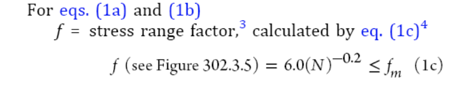
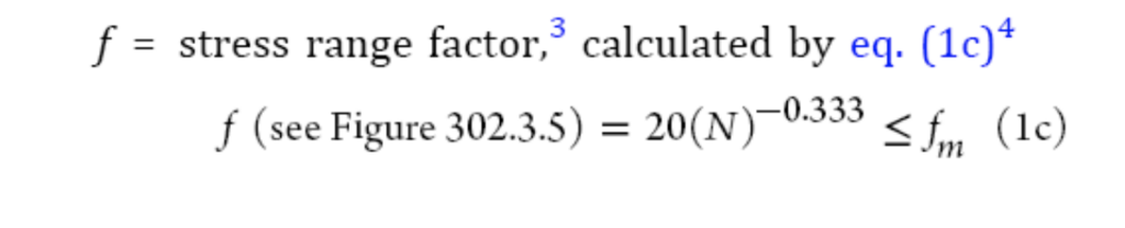
The slope of the curve for the stress range factor (f) was changed from a slope of 5:1 to a slope of 3:1 based on testing that shows using a fatigue curve with a slope of 3:1 is more accurate than the Code’s previous fatigue curve with a slope of 5:1.
2020 Code:
2022 Code:
Double Seated Valves (307.2.3) – New Section
Double seated valves larger than DN 50 (NPS 2), the designer shall determine if a change in fluid temperature or a change in fluid phase could result in a pressure–temperature condition between the valve seats above the pressure–temperature rating of the valve. Under such conditions, one of the following requirements shall be met:
a. Valves shall be equipped with a means to relieve the internal body cavity pressure (e.g., self-relieving seat design or relief device).
b. Valve cavity design shall be substantiated by one or more of the means stated in paras. 304.7.2(b) through 304.7.2(d) for the increased pressure–temperature condition.
Fillet and Socket Welds (328.5.2) – Added Fillet Weld Criteria
For any single continuous fillet weld greater than 5 mm (3∕16 in.), the weld may be less than the specified fillet weld size by not more than 1.5 mm (1∕16 in.), provided the total undersized portion of the weld does not exceed 10% of the total length of the weld or 50 mm (2 in.), whichever is less.
Fabricated Laps (328.5.5) – Added Criteria
Fabrication shall be in accordance with the following requirements:
a. Minimum weld dimensions shall be in accordance with those shown in Figure 328.5.5.
b. Welds shall be full penetration.
c. Corner groove welds shall be finished with cover fillet welds having a minimum throat dimension of 0.707(T − c).
d. Final machining of laps may be completed after welding.
Postweld Hydrogen Bakeout (300.2 & 331.1.2) – New Definition and Section
300.2: Definition
postweld hydrogen bakeout: holding a completed or partially completed weld at an elevated temperature below 425°C (800°F) to facilitate hydrogen diffusion from the weld.
331.1.2(c): Procedure
Postweld hydrogen bakeout performed at a temperature colder than that required by Table 331.1.1 (or the alternates as allowed by Table 331.1.2) is not considered PWHT. Separate procedure qualifications are not required when a postweld hydrogen bakeout is performed.
Lower Temperature Limits, Listed Materials (Table 323.2.2A) – Changed Values
Curve A, C and D have values updated which may result in a different MDMT than in the 2020 code.
Weld Acceptance Criteria (Table 341.3.2) – Added 8%
Cumulative length ≤ 4Tw in any 150mm (6 in.) weld length or 8% of total weld length, whichever is less.
Examination Personnel Qualification (342.1) – Added Alternate Methods
Expanded how qualifications can be established for NDE.
Personnel performing nondestructive examination to the requirements of this Code shall be qualified and certified for the method to be used in accordance with their employer’s written practice. The written practice shall be based on the training, examination, and experience requirements of one of the following:
(a) ASME BPVC, Section V, Article 1
(b) ASNT CP-189
(c) ASNT SNT-TC-1A
(d) other national or international central certification programs or standards
Other Test Requirements (345.2.2(d)) – Added Test Gages
(d)Test Gages
1. One or more pressure-indicating gages shall be connected to the piping in a manner in which they will receive full test pressure.
2. Dial indicating pressure gages used in leak testing should be graduated over a range of about double the intended test pressure, but in no case shall the range be less than 1½ nor more than 4 times the test pressure.
3. Digital reading pressure gages having a wider range of pressure may be used, provided the readings give the same or greater degree of accuracy as obtained with dial pressure gages.
4. The level of accuracy for pressure test gages should be specified in the engineering design.
5. Each gage shall be calibrated against a standard dead weight tester or a calibrated master gage. The gage shall have been calibrated within 12 months prior to each test, or any time there is reason to believe the gage is in error. Calibration may exceed 12 months with owner’s approval.
Pneumatic Leak Test Preliminary Check (345.5.5) – Changed Joint Checks
Changed the requirement for a check of mechanical joints during the preliminary leak check to a requirement of checking all joints, including welded and bonded joints.
2020 Code:
… or 170 kPa (25 psi) is attained, at which time a preliminary
check shall be made, including examination of joints in
accordance with para. 341.4.1(a).
2022 Code:
… or 170 kPa (25 psi) is attained, at which time a preliminary
leak check shall be made of all joints.
Flanged Joints (F312.1) – Added External Load Qualifications
(a)(2) consideration of external loads. ASME BPVC, Section VIII, Division 1, UG-44(b) provides one acceptable method for qualifying piping external loadings on welding neck flanges in accordance with ASME B16.5 or ASME B16.47. Nomenclature should be as defined as in UG-44(b), except as follows:
a. PD = maximum operating pressure at operating temperature for the condition being analyzed
b. PR = flange pressure rating at design temperature (ASME B16.5 or ASME B16.47)